SIM808 Module – GSM (2G, 3G, 4G Sim Card), GPRS and GPS
KShs3,500.00
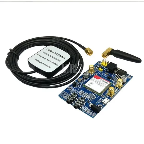
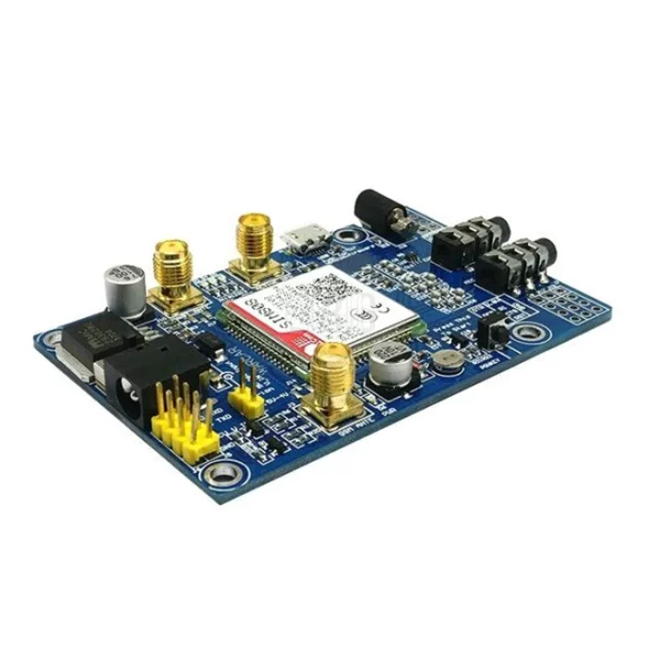
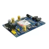
This Development Boards offers multichannel connectivity from Raspberry Pi Boards to the SIM808 module.
The SIM808 module features quad-band GSM/GPRS communication, enabling global operation on multiple frequency bands. It also includes a built-in GPS receiver for accurate real-time positioning, making it suitable for tracking applications. With a compact form factor, it integrates easily into various devices. The module offers various communication interfaces, such as UART and I2C, along with GPIO pins for versatile connections. It communicates using AT commands, simplifying integration with external microcontrollers or host systems. Ideal for IoT projects, asset tracking, and location-based services.
See below description for the various specification of the development board and its operations. There is also this tutorial which can help with basic testing and getting started
Out of stock
Development Board Specifications:
- Three Power Input Interfaces: DC044 and V_IN interface and one lithium battery interface.
- Note: The range of DC044 and the pin voltage input v_in is 5-26 v, when using 5 v as the power, make sure that the power supply can supply a current 2A. The input power voltage range of lithium battery is 3.5-4.2 v.
- Switch: It is used to open / close the input power supply for the module. When in use, please confirm switching to open state (near board inside).
- SMA Antenna Interfaces: There is a GSM antenna interface, an onboard GPS antenna interface and a BT antenna interface.
- Start Button: The module has a start button.
- Note: When the board is on, the power (pwr) LED lights up. When you long press (about 2 seconds) on the start button, the other three LEDs will light up. One of them will begin to flash; This suggests that the SIM808 module is starting up. If the power supply, gsm and gps antenna and sim card are connected to the module correctly, the LED will flash slowly (3 second to 1 second light), it indicates that the module is registered in the network, and you can make a call or do something else.
- TTL Serial Relationship: The module offers a TTL level relationship.
- Note: The vmcu pin is used to control the high level of TTL UART, so as to realize to match 1.25 v / 3.3 v / 5 v systems. For example, if you want to use 5V mcu to control this card, the vmcu pin must be connected to dc5v. And if you use mcu stm32, the vmcu pin should be connected to dc3.3v. The rxd pins are the sim808 rxd and the txd pins are the sim808 txd. The v_in pin can connect power, the function of this pin has the same function as dc044.
- USB Interface: This interface is for use only to update the sim808 module firmware.
Operation Description:
- Preparation:
- Shield sim808
- Dc9v adapter
- USB-TTL module or other tools.
- Computer Software
- Hardware Settings
- Connect USB-TTL to UART interface
- USB-TTL sim808
- Txd rxd
- Rxd txd
- Gnd gnd gnd
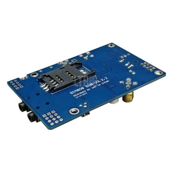
- Insert valid SIM card to simcard holder.
- Connect the GPS antenna and GSM antenna to the board
- Connect the power adapter to the dc044 interface
- Change the switch
- Press the powkey button for 2 seconds, the sim808 module will work and the other 3 LEDs will light up.
- Connect USB-TTL to UART interface
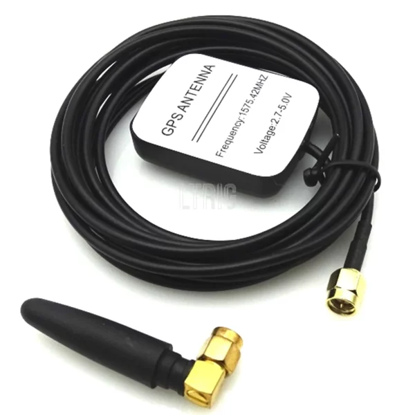
Package includes:
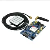
1 x Sim808 Development Board
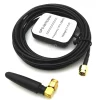
1 x GSM Antenna
1 x GPS Antenna
Only logged in customers who have purchased this product may leave a review.


Reviews
There are no reviews yet.